Each transformer construction and application is different, requiring its own unique approach and test plan.
Determining the existing condition of power transformers is an essential step in analyzing the risk of failure. The following is a summary of testing and diagnostic techniques and tools used to assess the condition of transformers.
A transformer maintenance program must be based on thorough routine inspections. These inspections must take place in addition to normal daily/weekly data gathering trips to check oil levels and temperatures. Some monitoring may be done remotely using supervisory control and data acquisition (SCADA) systems, but this can never substitute for thorough inspections performed by qualified electrical maintenance personnel.
Not all of the listed tests are performed at the factory, and not all of them are performed in the field. Each transformer construction and application is different, requiring its own unique approach and test plan.
Online Transformer Tests
These diagnostic inspections are performed while the transformer in service (online):
1. Dissolved Gas Analysis (DGA)
A DGA is the first indicator of a problem and can identify deteriorating insulation and oil, overheating, hot spots, partial discharge, and arcing. This is by far the most important tool for determining the health of a transformer.
The DGA test measures dissolved gases in the transformer oil and is capable of detecting: arcing, bad electrical contacts, hot spots, partial discharges, overheating of conductors, oil, tank, and cellulose (paper insulation) degradation. Samples are generally sent to a laboratory for analysis, but portable equipment is available to perform the test in the field.
Related: Specific Gravity of Transformer Oil, Where to Draw Your Sample
2. Oil Physical and Chemical Tests
In addition to the DGA test, additional oil samples can be taken to detect moisture, interfacial tension, acidity, furans, dissolved metals, and metal particle count (indicating pump problems). Samples are usually sent to a laboratory for transformer oil analysis.
Related: Insulating Liquids: Basic Properties, Types and Applications Explained
3. Physical/Visual Inspection - External
Safely evaluate the transformer exterior for:
- oil leaks
- broken parts
- worn paint
- defective support structures
- malfunctioning temperature and level indicators
- cooling system problems
- pump and radiator problems
- bushing and lightning arrester porcelain cracks, etc.
Related: 3 Routine Inspections and Checks for Liquid Filled Transformers
4. Infrared Scan
In addition to visual inspections, a thermographic camera can be used to quickly detect hot spots, localized heating, bad connections, circulating currents, blocked cooling, tap changer problems, bushing, and lightning arrester problems.
Related: Infrared Thermography for Electrical Distribution Systems
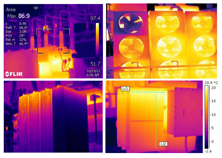
Infrared scans are extremely effective in detecting problems that can lead to early failure in transformers.
5. Ultrasonic and Sonic Contact Fault Detection
A fault detector equipped with a data logger can be used to detect internal partial discharge, arcing, sparking, pump impeller, and bearing problems. This test is also useful in pinpointing mechanical noises and loose parts (blocking, deflectors, etc.). Care should be taken because this method requires contact with the transformer while energized.
6. Ultrasonic Non-Contact and Contact Fault Detection
Non-contact ultrasonic detectors can be used to easily detect nitrogen leaks, vacuum leaks, corona at bushings, pump mechanical and bearing problems, and cooling fan problems.
7. Vibration Analysis
Data loggers equipped with accelerometers and other vibration analysis tools can be attached to the transformer exterior to detect internal core vibration, shield problems, and loose parts.
8. External Temperatures (Main Tank)
Portable temperature data loggers and software can be used to monitor temperature changes with variations in load and ambient temperature.
9. Sound Level Tests
Measure internal and external noises using a sound level meter and compare them to baseline readings and other vibration tests.
While transformer cores are generally recognized as the main source of transformer sound, electromagnetic forces in the windings, known as load noise, can also be a significant influence in low sound level transformers, among other electrical and mechanical factors.
Related: Transformer Humming Noise Explained
10. Corona Detection
Corona (air ionization) may be visible at the tops of bushings at twilight or night, especially during periods of rain, mist, fog, or high humidity. Use a corona scope to compare bushings and surge arresters, and all other high-voltage connections with sister units.
Offline Transformer Tests
The following diagnostic tests are performed while the transformer is not in service (offline) and has been isolated for safety:
1. Doble Power Factor
A good indication of insulation deterioration is a slowly rising power factor. Doble insulation testing is an important step in determining the condition of the transformer because it can detect loss of winding insulation integrity, loss of bushing insulation integrity, and winding moisture.
Related: 3 Basic Modes of Power Factor Testing Explained
To keep failures at a minimum, periodic maintenance testing of the insulation is recommended to indicate whether it is deteriorating, and how fast.
2. Excitation Current
Doble test equipment is also used to conduct excitation current tests, which can detect short-circuited turns, poor electrical connections, core delaminations, core lamination shorts, tap changer problems, and other possible core and winding problems. The results, as with all others, should be compared with factory and prior field tests.
3. Turns Ratio (TTR)
The turns ratio test detects shorted turns, which indicate insulation failure by determining if the correct turns ratio exists. Shorted turns may result from short circuits or dielectric (insulation) failures.
This test only needs to be performed if a problem is suspected from the DGA, power factor testing, or a protective relay operation. This test can be performed using a turns ratio tester or by applying a reduced test voltage to the secondary and measuring the induced voltage on the primary. This test can also verify that the winding polarity is correct.
Related: Introduction to Transformer Turns Ratio Testing
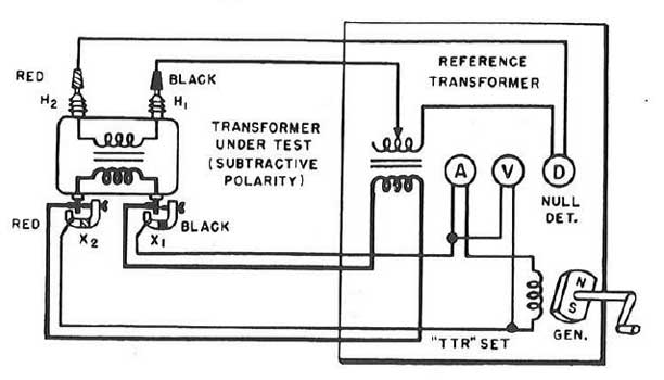
When testing a transformer for turns ratio, the connections is determined by matching parallel vectors. Photo: Megger.
4. Leakage Reactance
This is normally an acceptance test to ensure that the nameplate percent impedance matches the measured percent impedance when the transformer arrives from the factory.
Percent impedance/leakage reactance testing is performed by short-circuiting the low-voltage winding and applying a test voltage to the high-voltage winding using a power factor test set.
5. Sweep Frequency Response Analysis
These tests show, in trace form, the winding transfer function of the transformer and are valuable for determining if any damage has occurred during shipping or during a through fault. Structural problems, movement of core and windings, core grounds, core displacement, and other core and winding problems can be revealed by this test.
A sweep frequency analyzer is used to place a signal on each of the high voltage windings, and the signal is detected on the low-voltage windings. This provides a picture of the frequency transfer function of the windings. If the windings have been displaced or shifted, test results will differ markedly from prior tests.
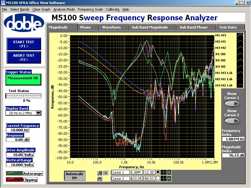
Sweep Frequency Response Analysis detects structural problems, movement of core and windings.
6. Winding Resistance (Across Winding)
A Wheatstone or Kelvin bridge can be used to check for loose connections on bushings or tap changers, broken strands, and high contact resistance in tap changers. Results are compared to other phases in wye-connected transformers or between pairs of terminals on a delta-connected winding to determine if a resistance is too high.
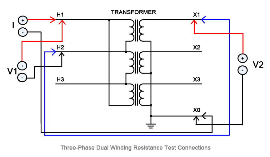
Winding resistance measurements are an important diagnostic tool for assessing possible damage to transformers resulting from poor design, assembly, handling, unfavorable environments, overloading, or poor maintenance.
Related: Transformer Winding Resistance: Test Methods and Procedures Explained
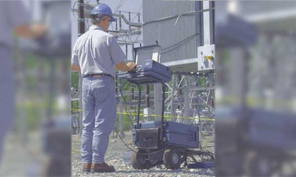
7. Winding Insulation Resistance (PI)
Insulation resistance tests are made to determine the dielectric strength of individual windings to ground or between individual windings. Insulation resistance tests are commonly measured directly in megohms or may be calculated from measurements of applied voltage and leakage current.
The recommended practice in measuring insulation resistance is to always ground the tank (and the core). Short circuit each winding of the transformer at the bushing terminals. Resistance measurements are then made between each winding and all other windings grounded.
Related: Insulation Resistance Test Methods, A Beginners Guide
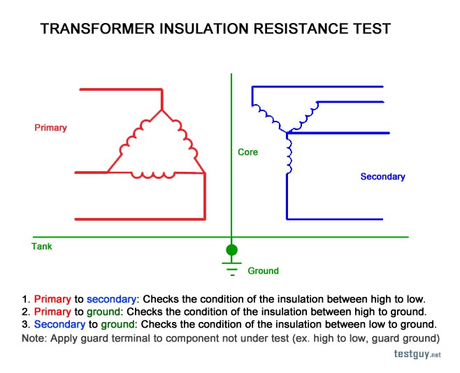
Sample transformer insulation resistance test procedure. Photo: TestGuy.
It is recommended that insulation resistance values be measured periodically (during maintenance shutdown) and plotted. Substantial variations in the plotted insulation resistance values should be investigated for the cause.
The polarization index is a ratio of the insulation resistance at the end of a 10-minute test to that at the end of a 1-minute test at a constant voltage. As a general rule of thumb, values less than 1 are dangerous; 1.1 - 1.25 is questionable; 1.25 - 2.0 is fair; and anything above 2.0 is considered good.
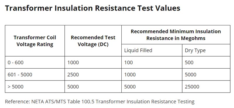
Recommended test values for transformer insulation resistance and PI testing. Photo: NETA.
8. Core to Ground Resistance
This test is used if an unintentional core ground is suspected, as may be indicated by the DGA test. A megohmmeter is attached between the core ground lead (or the top of the core itself and the tank) and ground. The Megger is used to place a DC voltage between these points, and the resistance is measured.
Related: Basic Test Equipment: Insulation Resistance Tester
The intentional core ground must be disconnected to perform this test. Some may find this to be difficult, and some oil might have to be drained to accomplish this. On some transformers, core ground conductors are brought outside through insulated bushings and are easily accessed.
A new transformer should read greater than 1,000 megohms. A service-aged transformer should read greater than 100 megohms. Ten to one hundred megohms is indicative of deteriorating insulation between the core and ground. Less than 10 megohms is sufficient to cause destructive circulating currents and must be further investigated.
9. Internal Inspections and Tests
The interior construction of the transformer can be inspected for oil sludging, displaced winding or wedging, loose windings, bad connections, and burned conductors. Many times, more damage is done by opening a transformer and doing an internal inspection than what is gained.
Related: Types and Construction of Power and Distribution Transformers
If an internal inspection is absolutely necessary, it must be completed by an experienced technician who knows exactly what to look for and where to look.
10. Degree of Polymerization
One of the most dependable means of determining paper deterioration and remaining life is the DP test of the cellulose. Do not open a transformer for the sole purpose of doing this test. Perform this test only if the unit is being opened for other reasons.
When conducting an internal inspection, or if the transformer is opened and oil is fully or partially drained for any reason on a service-aged transformer, perform a DP test by removing a sample of the paper insulation about 1 centimeter square from a convenient location near the top of the center phase with a pair of tweezers. Send this sample to an oil testing laboratory for analysis.
Transformer Diagnostic Tests by Component
A summary of diagnostic techniques for each transformer component (adapted from IEEE 62) is given below:
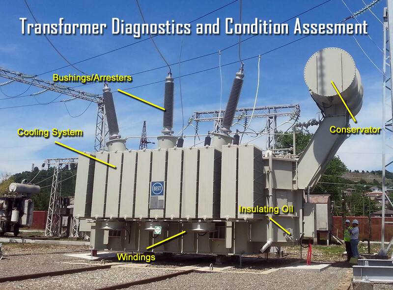
Windings
- DC Resistance
- Turns Ratio (TTR)
- Percent Impedance/Leakage Reactance
- Sweep Frequency Response Analysis
- Doble Tests (for windings and oil)
- Capacitance
- Excitation current and watt loss
- Power factor/Dissipation factor
Bushings and Arresters
- Capacitance (Doble Tests)
- Dielectric Loss (watts)
- Power Factor
- Temperature (infrared scan)
- Oil Level (bushings only)
- Visual inspection for porcelain cracks and chips
Related: High-Voltage Bushing Maintenance and Test Procedures Explained
Insulating Oil
- Dissolved Gas Analysis
- Dielectric Strength
- Metal Particle Count (for suspected pump problems)
- Moisture
- Power Factor/Dissipation Factor (Doble)
- Interfacial Tension
- Acid Number
- Furans
- Oxygen Inhibitor
Core
- Insulation Resistance
- Ground Test
Conservator
- Visual (oil leaks and leaks in diaphragm)
- Inert Air System (desiccant color)
- Level Gauge Calibration
Tanks and Auxiliaries
- Fault Pressure Relay (functional test)
- Pressure Relief Device (visual)
- Buchholz Relay (visual check for gas)
- Top Oil Temperature Indicator
- Winding Temperature Indicator
- Infrared Temperature Scan
- Fault Analyzer (ultrasonic)
- Sound Analysis (sonic)
- Vibration Analysis
Cooling System
- Clean (fan blades and radiators)
- Fans and Controls (check fan rotation)
- Oil Pumps (check flow indicators, check rotation)
- Pump Bearings (vibration, sound, and temperature)
- Check Radiator (valves open)
- Thermographic (IR) scan of cooling system
Related: Transformer Cooling Systems and Methods Explained