An electric motor is the workhorse that converts electrical energy into mechanical energy using the principles of electromagnetism. These rotating machines are used in nearly every form of modern life, from simple residential appliances to large industrial facilities and manufacturing plants.
Children’s toys, vacuum cleaners, fans, power tools, electric vehicles, mechanical pumps, elevators, and freight trains are just a few examples of the wide range of applications where you will find some form of electric motor. Magnetic fields created by electrical charges are the driving force behind motors that generate the torque required to perform useful work.
With so many different uses for motors and the wide variety of electrical systems that power them, it should come as no surprise that there are many different performance ratings and operating characteristics that must be taken into consideration when choosing an electric motor for a particular application.
In an effort to standardize these basic performance and operating parameters of a motor, the National Electrical Manufacturers Association (NEMA) takes the lead in defining these ratings in NEMA Standard MG-1. The operating characteristics defined in this standard are coded onto the motor nameplate at the time of manufacture to help guide the end user with safe and reliable application.
The National Electrical Code specifies the required markings for usual motor applications in NEC Section 430.7(A) for safe installation and operation in specific environments. When it comes to testing and maintenance of electrical motors, a solid understanding of these ratings is paramount in order to determine test procedures and expected test values of a particular machine.
In this article, we explain the markings found in NEC along with other common terms and ratings included on motor nameplates.
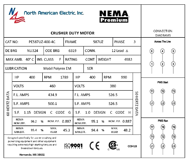
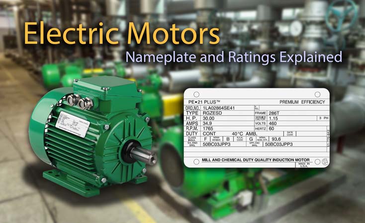
Electric Motor Nameplate Example. Photo: North American Electric
Motor Nameplate Ratings
- Manufacturer
- Voltage Rating
- Full-load current (FLA)
- Rated Frequency and Number of Phases
- Synchronous Speed
- Rated Full Load Speed
- Slip
- Horsepower (HP)
- Motor Efficiency
- Service Factor
- Rated Temperature Rise, Insulation System Class, and Rated Ambient Temperature
- Time Rating
- Code letter or locked-rotor amperes
- Design Letter Code
- Field current and voltage
- Winding
- Thermally Protected
- Enclosure Type
- Frame Size
- Heater Voltage
Manufacturer
Indicates which company produced the motor and will typically include the company address and country of origin. The manufacturer will generally have a specific model or production number associated with the motor.
Voltage Rating
Indicates the operating voltage required for optimal performance as intended by the motor manufacturer. Rotating machines are typically designed with a 10% tolerance for voltage above and below the rated nameplate value.
The voltage tolerance is generally not listed on the motor, which can lead to confusion for those who are unfamiliar with this rating. A motor with a rated nameplate voltage of 460V should be expected to operate between 414V and 506V. A 230-volt motor can work within the range of 207V to 253V.
Some motors can operate with more than one voltage, and this capability will be indicated on the nameplate. Dual voltage ratings allow for the stator windings to be split in half to be used in either a series or a parallel connection.
It is important to note that many of the other ratings found on the nameplate, such as power factor, efficiency, torque, and current, only apply at rated voltage and frequency.
Full-load current (FLA)
As the connected load and required torque on an electric motor increases, the amperage required to power the motor also increases. The full-load current (FLA) is the maximum expected amperes drawn by the motor when operating at maximum torque and horsepower.
The nameplate FLA is a very important rating that is used to select the correct wire size, motor starter, and overload protection devices necessary to serve and protect the motor. For a multispeed motor, the full-load current is only listed for the maximum speed.
To calculate the voltage drop of a motor circuit, take the feeder circuit resistance and multiply it by the motor FLA. For percent voltage drop, divide the previously obtained value by the open-circuit supply voltage and multiply by 100%.
Rated Frequency and Number of Phases (AC Motors)
The frequency of a power system refers to the number of times that an AC sinusoidal voltage wave repeats the same sequence of values within a specified unit of time. In the USA and Canada, the power system frequency is 60 Hz.
In other parts of the world, the frequency may be either 50 Hz or 60 Hz. The number of phases refers to whether the motor is connected to a single live conductor and neutral (single-phase) or three live conductors (three-phase).
Synchronous Speed
The speed at which the rotating field inside the motor operates depends on the input power frequency and the number of electrical magnetic poles inside. This is called the synchronous speed, which is independent of the output shaft speed.
Synchronous Speed = Number of cycles (Hz) x 60 (seconds in 1 min) x 2 (cycle pulses) / number of poles.
A four pole motor with no load connected, for example, would have a synchronous speed of 1,800 RPM at 60Hz and a synchronous speed of 1,500 RPM at 50 Hz. If a motor is designed to operate at different speeds when controlled by a variable frequency drive (VFD), the input frequency range must be displayed on the nameplate.
Rated Full Load Speed
It’s nearly impossible for a motor to reach synchronous speed because even an unloaded motor still has some form of friction to overcome. As the motor load increases, a higher torque is required, implying a reduction in the revolutions per minute.
The rated full load speed is the actual RPM value listed on the motor nameplate. The term “slip” refers to the difference between the synchronous speed and actual full load speed (also referred to as the asynchronous or slip speed).
Slip
The difference between the synchronous speed of the electric motor magnetic field and the shaft rotating speed is slip, measured in RPM or frequency. Slip is typically expressed as the ratio between the shaft rotation speed and the synchronous magnetic field speed.
Slip increases with load, providing greater torque. To calculate motor slip in terms of percentage, subtract the asynchronous speed from the synchronous speed, then divide by the synchronous speed and multiply by 100.
Slip = ( (synchronous speed – actual speed) / synchronous speed ) x 100
Using the formula above, a motor with a rotational speed of 1400 RPM and a synchronous speed of 1500 RPM would have a slip of 6.7%
When the rotor is not turning, the slip is 100%. Full-load slip varies from less than 1% in high hp motors to more than 5-6% in minor hp motors.
Horsepower (HP)
The most basic and common rating for an electric motor is its horsepower rating, which was originally adopted in the late 18th century by Scottish engineer James Watt, who wanted to compare the output of steam engines with the power of draft horses.
This term was created to help customers better understand how much work steam engines could produce. It was later expanded to include the output power of other types of piston engines, as well as turbines, electric motors, and other machinery.
Shaft horsepower is a measure of the motor’s mechanical output rating, expressed as its ability to deliver the torque required for the load at rated speed.
HP = (Torque) x (Speed) / 5250. Torque is expressed in lb-ft and Speed is expressed in RPM.
For an electric motor, one horsepower is equivalent to 746 watts of electrical power and is the standard rating in the United States. In Europe, the kilowatt rating of a motor has become standard.
1HP = 746 watts. A motor of 100HP will produce 74.6kW of electrical power. The horsepower rating is required by the NEC to be listed on the nameplate for motors greater than 1/8 HP.
Motor Efficiency
An indication of how much electrical energy supplied to the motor is converted to output shaft mechanical energy, expressed in percentage. The remaining thermal energy that is not converted to mechanical energy is lost primarily in the form of heat, which can be damaging to the motor insulation.
Efficiency is defined as output power divided by input power expressed as a percentage: (Output / Input) × 100.
Losses in the motor due to heat can have a dramatic effect on efficiency. There are five different types of motor losses:
-
Core Losses: The energy required to magnetize the core and eddy current losses in the stator core.
-
Stator Losses: I2R heating of the stator due to current flow in the stator windings.
-
Rotor Losses: I2 heating of rotor bars as induced current flows.
-
Friction and Windage Losses: Bearing and air friction on the rotor shaft and cooling fan.
-
Stray Load Losses: Leakage reactance fluxes induced by the load current.
The first three categories (core, stator, and rotor) typically make up more than 80% of the total motor losses.
Service Factor
The service factor of a motor (SF) is a measure of periodic overload capacity at which a motor can operate without overheating or otherwise damaging the motor when the rated voltage and frequency are supplied to the motor.
Motors that continuously operate at a service factor greater than 1 will have a reduced life expectancy compared to operating at its rated nameplate horsepower.
Example: A 1HP motor with a service factor of 1.15 can operate at 1.15hp without overheating (1×1.15)
Rated Temperature Rise, Insulation System Class, and Rated Ambient Temperature
NEMA specifies the allowable temperature rise for motors operating under full load and at service factor, if applicable. The specification is standardized on an ambient temperature of 40°C or 104°F for all insulation classes.
Each class of insulation has a maximum motor winding temperature rise and a maximum temperature rating. In addition, a hot spot temperature rise is specified, which pertains to motor windings that are surrounded by other windings.
Allowable temperature rise at full load for motors with a service factor of 1.0
- Class A Insulation – 60°C, 5°C Hotspot
- Class B Insulation – 80°C, 10°C Hotspot
- Class F Insulation – 105°C, 10°C Hotspot
- Class H Insulation – 125°C, 15°C Hotspot
Allowable temperature rise at service factor for motors with a service factor of 1.15
- Class A Insulation – 70°C
- Class B Insulation – 90°C
- Class F Insulation – 115°C
Maximum motor winding insulation temperature
- Class A Insulation – 105°C
- Class B Insulation – 130°C
- Class F Insulation – 155°C
- Class H Insulation – 180°C
Example: For a Class F insulated motor with a service factor of 1.0, add the NEMA allowable rise of 105°C to the reference temperature of 40°C to obtain the motor max operating temperature (105 + 40 = 145°C).
The NEMA specified maximum temperature rating is higher than the allowable temperature rise to give headroom for the winding “hotspot” temperature, in this case, 10°C for a class F machine.
Class F motors have traditionally been used for in most industrial applications. With the increasing use of AC variable drives (VFD) and the associated heating caused by the harmonics produced in these drives, Class H is now much more common.
Time Rating
Electric motors have a time rating that indicates how long they can operate at their rated load and ambient temperature. Standard motors are rated for continuous duty, which can be operated around the clock (24/7) without interruption.
Depending on the application, some motors may only be rated to operate for a short duration. Motors with a reduced time rating can be manufactured with lighter-duty construction and will therefore be priced lower than a motor rated for continuous duty.
An example of an intermittent duty motor would be one used in a valve actuator. In many cases, mechanical valves are opened and closed periodically opposed to a pump motor which may run for many hours or days on end.
The time rating of an electric motor is usually expressed in minutes. Some examples of time ratings are 5, 15, 30, 60 minute intermittent duty.
Code letter or locked-rotor amperes
Electric motors typically have a large inrush current associated with them when started with their full voltage rating applied to the windings. In many cases, this starting current is many times greater than the value of the full-load current.
The locked-rotor value is important because large inrush current can lower the voltage supplied to the motor which may affect other equipment on the same circuit. Reduced voltage and wye-delta motor starters can help limit this inrush current by applying a lesser voltage to the motor for a brief period of time to while the motor gains speed before applying full rated voltage.
Locked rotor refers to the kVA per HP that will be drawn when the rotor is locked in place. Code letters for this rating will range from A to V, with Class A motors having the lowest kVA rating and Code V motors having the highest.
Standard locked current ratings can be found in Article 430 of the NEC. This rating is required when an AC motor rated 0.5 hp or more. On polyphase wound rotor motors, the code letter is usually omitted.
Design Letter Code
Electric motors are assigned a design letter code specified by NEMA which defines the torque and current characteristics of the motor. Some machinery may require motors with specialized performance indicated by this code.
- Code A – Normal starting torque, high starting current
- Code B – Normal starting torque, low starting current
- Code C – High starting torque, low starting current
- Code D – High starting torque, low starting current, high slip
Motor design letter definitions are found in ANSI/NEMA MG 1-1993, Motors and Generators, Part 1, Definitions, and in IEEE 100-1996, Standard Dictionary of Electrical and Electronic Terms. NEMA Code B motors are the most widely used type of motor, and can start a wide variety of industrial loads.
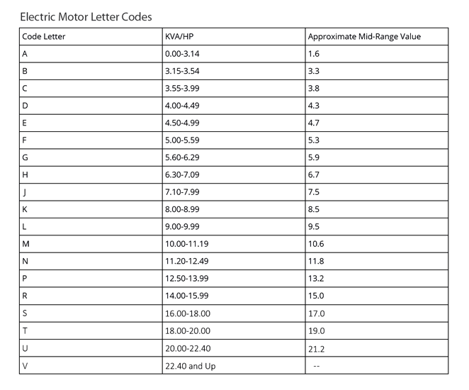
Electric Motor Design Letter Codes. Photo: TestGuy.
Field current and voltage
For DC excited synchronous motors, the rated field current and voltage will be listed on the nameplate.
Winding
The type of winding construction used for an electric motor such as straight shunt, stabilized shunt, compound, or series, if a dc motor.
Thermally Protected
Motors that are provided with a thermal protector are indicated on the nameplate, either marked “Thermally Protected” or “T.P.” This type of protection interrupts power to the motor if the motor experiences excessive temperatures from overload or a failure to start. Power is reconnected once the motor has cooled down to an acceptable temperature.
Enclosure Type
Often shown as “ENCL” on a nameplate, the enclosure type classifies the degree of protection the motor has from the operating environment, and the method of cooling. Standard motor enclosure types include:
-
Open Drip Proof (ODP) - only suitable for indoor environments which are clean and dry.
-
Totally Enclosed Fan Cooled (TEFC) - typically used in outdoor and dirty locations but is not air-tight or water-tight. The amount of water and outdoor air permitted to enter the motor does not affect operation.
-
Totally Enclosed Non Ventilated (TENV) - used where exposed to dampness or dirt and is not equipped with a fan for cooling. These motors use natural convection to cool and must not be used in hazardous locations, or where there is excessive moisture.
-
Totally Enclosed Air Over (TEAO) - dust-tight enclosure designed for blowers and fans mounted on shafts. The motor must be mounted on the shaft itself, in line with the airflow.
-
Totally Enclosed Wash Down (TEWD) - designed for high-pressure jets of water and high humidity. This enclosure type is a top choice for wet environments.
-
Totally Enclosed, Hostile and Severe Environment – designed for non-hazardous environments with an extreme presence of moisture or chemical agents.
-
Explosion-Proof (EXPL) – designed to withstand internal explosions of specified gases or vapor without allowing the explosion to spread to the external atmosphere.
-
Hazardous Location (HAZ) - A general classification for hazardous locations. These motors are further subdivided by Class, Division, and Group.
Frame Size
Motor dimensions are indicated by the frame size and sets important mounting dimensions such as foot hole mounting pattern, shaft diameter, and shaft height.
Heater Voltage
Motors used in outdoor installations or in locations where condensation might occur often come equipped with condensation prevention heaters. This type of equipment is usually marked with the rated heater voltage, number of phases, and the rated power in watts.
Condensation heaters are energized when the motor is turned off. NFPA 70-2017 Article 430.7(A)(15) requires the manufacturer to mark a motor equipped with a condensation heater to alert the installer to provide the proper electrical supply to the heater.